You can name the gauges, but can you explain why the altimeter and vertical speed indicator might become unreliable together? For private pilot study, connect each indication to the question it answers and the system behind it. That makes the panel easier to understand when the information disagrees.
This introduction uses a conventional light-airplane panel. Actual installations, power supplies, markings and procedures differ. Read the FAA's PHAK Chapter 8: Flight Instruments, then use your airplane's POH/AFM and equipment supplements with your instructor.
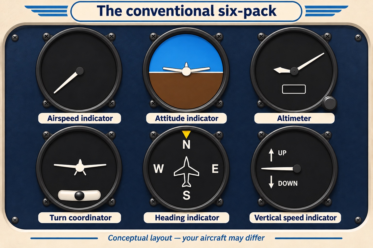
AI-generated recognition diagram. Dial faces are schematic, without calibrated readings or aircraft operating limits; use the actual panel and approved manual to learn those details.
Learn the six questions first
- Airspeed indicator: What indicated airspeed is the airplane showing? It compares pitot and static pressures; it does not directly display groundspeed.
- Attitude indicator: What pitch and bank attitude is indicated relative to the horizon? It does not by itself establish the flight path.
- Altimeter: What altitude is indicated for the selected pressure setting? It does not directly measure height above nearby terrain.
- Turn coordinator: What roll or turn tendency is indicated? In a steady turn it shows turn rate, not a measured bank angle. The ball indicates coordination.
- Heading indicator: Where is the airplane's nose pointing? Heading and ground track can differ in wind.
- Vertical speed indicator, or VSI: What rate of climb or descent is indicated? Conventional instruments have response lag.
Use the image to find the conventional positions, then cover the labels and explain each question aloud. Add a separate note about the magnetic compass: a conventional unslaved heading gyro needs periodic comparison and alignment with the compass under suitable conditions.
Group instruments by their sources
In a conventional pitot-static installation, the airspeed indicator uses both pressure sources, while the altimeter and VSI use static pressure. That shared source helps explain why one blockage can affect several instruments.
Mechanical gyro instruments can be vacuum-driven or electrically driven. A common training-airplane arrangement supplies the attitude and heading gyros from vacuum and the turn coordinator electrically, but it is not universal. The FAA's aircraft systems chapter provides the broader system context.
Make a panel map for your actual airplane: instrument, sensor or pressure source, power source, failure indication and backup. Ask your instructor to verify every entry. The useful result is knowing your installation, rather than assuming every airplane with round gauges is wired the same way.
Work through a hypothetical static blockage
Imagine the conventional static source becomes completely blocked, with no alternate source selected and the pitot source still working. During a subsequent climb, trapped static pressure leaves the altimeter stuck near the blockage altitude, and the VSI settles toward zero. The airspeed indication also becomes inaccurate.
For a classroom exercise, draw the pressure plumbing and trace which instruments share the blocked source. Compare this with a problem limited to the pitot opening: the exact airspeed behavior depends on which openings, including the drain, are blocked. Avoid memorizing one result for every “blocked pitot” question.
In actual flight, use trained aircraft-control skills, cross-check available information and follow the aircraft's approved abnormal procedure. Ask your instructor to demonstrate any alternate-static system and its correction guidance in an appropriate training setting. This example is a reasoning exercise, not an aircraft-specific checklist.
Recognize the same functions on glass
A primary flight display can present airspeed and altitude tapes, attitude, heading and vertical speed on one screen. An air data computer processes pressure information; an attitude and heading reference system, or AHRS, supplies attitude and related reference information. A screen layout does not make these measurements independent of their sensors or power supplies.
Locate the standby instruments, failure flags and approved reversionary modes in your airplane's documentation. For your next lesson, ask what a display failure would remove compared with a sensor failure. Bring the answer back to your panel map.
Practice an explanation in AirspaceLab
In free flight, compare the available flight indications during a gentle simulated climb, level-off and turn. Explain altitude, vertical speed and heading as different quantities. AirspaceLab is not a trainer for your airplane's complete avionics or failure procedures.
Then use the MSL vs AGL article and sectional chart guide to connect an altitude indication with the airspace decision. Finish by naming one instrument limitation and one source you will verify in the POH/AFM.
Sources checked: November 14, 2026. Reference: FAA-H-8083-25C, Chapters 7 and 8. The blockage scenario and image are conceptual; actual aircraft procedures and limitations take precedence.